The Prius transmission includes a special gear set that Toyota call the "Power Split Device" (PSD). This is an "epicyclic" or "planetary" gear, similar to those used in automatic transmissions. However, its use in the Prius is very different, as I hope to explain.
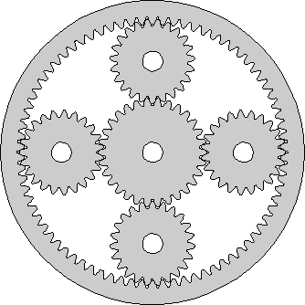
In the picture at right, I have tried to show how the gears of the PSD are arranged and how they mesh together. The gear in the center is called the "sun" gear. The gears surrounding it are called the "planets". (Another name used for this type of gear is "sun-and-planets".) The shafts of the planet gears are fixed to a "planet carrier", which can rotate around the same axis as the sun. This is not shown in the diagram. Around the outside is the ring gear, with its teeth pointing inwards and meshing with the planets. This also rotates around the same axis as the sun.
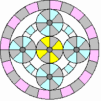
Most people have difficulty visualizing how the gears move in an epicyclic gear set. To help with this, I set about creating some animations. I tried first to animate the above diagram, but I quickly gave up and devised a different picture of a planetary gear. This is shown at left here. This simpler representation does not show the gear teeth. Instead, the "gears" roll against each other. The colored bars make it easier to see how each gear is moving. Looking closely, you can see that I've not cheated and the gears do not slip. The grey bars always line up with each other as the gears go around.
This particular animation shows the PSD when the ICE is accelerating the car. The sun gear is, obviously, yellow. The planet gears are blue. The white band with blue bars behind the planets represents the planet carrier. You should imagine that the planet shafts are fixed to this and see how the planet gears move around with the carrier as a whole as well as rotating on their shafts. The ring gear is "rose".
If you know how the differential gear in a car works and have a picture of it on your mind's eye, you might benefit from the sidebar How the Prius PSD is like a Differential. This explains how similar a planetary or epicyclic gear is to a differential and how you can, with a flexible enough imagination, transform one into the other. Since this approach to the PSD comes from Al, the Prius-Harley guy on the Yahoo! discussion group Prius_Technical_Stuff, it may help you out if my explanations don't strike home.
In Continuously Variable Transmission, I described how using the PSD allows the ICE to spin at a rate suitable for generating power independently of the vehicle speed. Because the ICE doesn't "rev-up" as the car goes faster, the car sounds as if it has a CVT. However, the torque multiplication effect of a true CVT is absent and it replaced by electric motor assist. I explained that the ICE output shaft is connected to the planet carrier of the CVT, that one of the motor/generators (MG1) is connected to the sun gear and that the ring gear drives the car via some reduction gears and the differential. The other motor/generator (MG2) is connected to the ring gear and adds its torque into the reduction gears. In this section, I hope to improve this explanation with emphasis on the power split device itself.
The gear diagram at the top of the page has the correct number of teeth for the Prius PSD. The sun gear has 30 teeth, each planet 23 and the ring gear 78 (on the inside!). The animation, however, takes huge liberties with gear ratios. I found that I could only make reasonably sized animated GIF files in a reasonable time by making the sun and planets the same size. Links in the explanations below will pop-up animations to supplement the text, but please do not use the animations to figure the actual ratios at which the sun, planet carrier and ring rotate in the Prius itself! Click here to get the gear diagram with the right number of teeth in a separate window.
There is a simple mathematical relationship between the rates at which the sun, planet carrier and ring rotate. The rate of rotation of the planets themselves is not interesting since there is no connection to their shafts from outside the PSD. Their rotation is an internal detail of the epicyclic gear set.
First, imagine the planet carrier held still and the ring gear making one clockwise revolution about the common axis (click for animation). 78 gear teeth, the number on the ring gear, pass by each planet. The planets are all forced to rotate clockwise by this number of teeth. Where each planet meshes with the sun gear, 78 teeth again pass by and the sun rotates by 78 teeth, but counterclockwise. Since the sun has 30 teeth around its circumference, to move by 78 teeth it must rotate by 78 / 30 = 2.6 revolutions. Using S to represent the number of rotations of the sun gear, R to represent the number of rotations of the ring gear and choosing clockwise as the positive direction, we have the relationship S = -2.6 * R if the planet carrier is held still.
Second, imagine the ring gear held still and the planet carrier making one clockwise revolution about the common axis (animation). This is a little more difficult, so let's take it in two steps. First, rotate both ring gear and planet carrier one revolution clockwise together. Fairly obviously, the sun gear will rotate one revolution clockwise as well as if the whole thing were glued together. Now, rotate the ring gear back counterclockwise to its starting point, leaving the planet carrier in its new position, to get the situation we wanted to consider. This is just the reverse of the first situation. The sun gear will rotate the same amount, 2.6 revolutions, but in the opposite direction, clockwise. So, when we have finished and got the ring gear in its starting position and planet carrier one rotation clockwise, we find that the sun gear has rotated one plus 2.6 equals 3.6 rotations clockwise. Introducing C to represent the number of rotations of the planet carrier, we have S = 3.6 * C if the ring gear is held still.
The final step is to acknowledge that if both the ring gear and planet carrier move, the rotation of the sun gear will just be the combination of the movements it would have made if each moved separately. Therefore, the full relationship is S = 3.6 * C - 2.6 * R.
Armed with the above equation, if we know the rotation rate of any two components of the PSD, we can find the rotation rate of the other. To see how this could be useful, let's replace the symbols for the sun, planet carrier and ring gear with symbols representing the motor/generators and internal combustion engine. The sun (S) is connected to motor/generator 1 (MG1). The planet carrier (C) is connected to the internal combustion engine (ICE). The ring (R) is connected to motor/generator 2 (MG2). Now we have:
Remember that the ring is also connected through the reduction gears and differential to the wheels. So, the ring rotation rate has a fixed relationship to the speed of the vehicle. If the car is traveling at a known speed, we can find the rotation rate of MG2 (using the reduction gear ratio and wheel radius). If we then want the ICE to turn at a certain r.p.m., to deliver the power we need with greatest efficiency, we can find the necessary rotation rate for MG1. Now we begin to see how the car's computers can set up the powertrain components to achieve the effects we discussed in Continuously Variable Transmission.
Before we dispense with mathematics and draw some more pictures, let's fit the speed of the car into the picture. The ring gear and MG2, we have said, connect to reduction gears which drive the differential which drives the axles which drive the wheels. The tooth ratios of the reduction gears result in a "final drive" ratio of 3.905 to 1. This means that MG2 has to rotate 3.905 times for the axles to rotate once. The differential does not change the rate of rotation between input and output except to compensate for the different inside and outside wheel distances when going around corners. The "rolling radius" of the Prius wheels and tires is about 11.1 inches. For each rotation of the axle, the car moves 2 * pi * 11.1 inches. Now we have enough information to figure out how the speed of the car relates to the rotation rate of MG2. Since arithmetic is either easy or boring, depending on your outlook, I'll just tell you the answer. If MPH represents the speed of the car in miles per hour, then:
For example, at 50 miles per hour, MG2 is spinning at 2955 r.p.m. From equation 1, if the computer wants the ICE to turn at 1500 r.p.m. at this speed, it must arrange for MG1 to run at -2283 r.p.m., that is 2283 r.p.m. backwards.
One final word - these equations always hold true. The constant 59.1 may change a bit if you let your tires go flat or change the them for a different type, but while the tire is gripping the road, these two equations always constrain the rotation rates of the ICE, MG1 and MG2.
Equations aren't much fun, are they? Fortunately, to understand how the Prius works, we don't really need to figure out the exact values for spin rates; a rough idea is almost always adequate. So, instead of using our calculators, we can use a picture called a "nomograph" to solve these equations approximately. A nomograph is a set of scales, that is, lines marked with numbers, drawn in a particular pattern. To use the nomograph, you draw a straight line passing through specific numerical values on a particular pair of scales. Where the line crosses the other scales allows you to read off the solution to your problem. For example, you could draw a nomograph for addition to solve the equation z = x + y. To use it, you would draw a line from a value on the x scale to one on the y scale and read off the answer on the z scale. With the same nomograph, you can solve any transposition of the original equation. In our addition example, you could also solve the subtraction x = z - y just by drawing the line between the z and y scales and reading the answer from the x scale. The nomograph for the Prius PSD will solve equation 1 and all transpositions of it. Because equation 2 is so simple and relates two quantities by a constant factor, the nomograph will solve that at the same time using two scales drawn back-to-back on the same line.
An explanation of the Prius PSD nomograph has been written by Robert Snyder and posted in the files section of the Yahoo! group toyota-prius. More than anything else, it was this document that started me on my quest to understand in detail how the Prius works. I will not be able to improve on Robert's description, so I will not attempt a full exposition. Instead, I will call upon the nomograph to solve particular problems. You can get the complete story from the original source (rather than clicking this link, try right clicking and storing the PDF file on your computer to print and study later).
At right is an example of the nomograph drawn the way I will use it in this topic area. The scale at the left side represents the rotation
rate of MG1. It is calibrated in revolutions per minute from 6500 backwards at the bottom to 6500 forwards at the top. These are
the safe limits for MG1, enforced by the Prius computers. 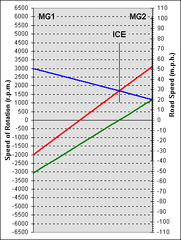 The thin line from bottom to top at the right is the scale representing the
rotation rate of MG2. To read this scale, you have to use the dotted
lines drawn across from the left hand scale (but the safe limit for MG2
is 6000 r.p.m.). Superimposed on this line is a thicker line representing
the road speed of the vehicle. The numbers on the right side of the
nomograph calibrate this scale in miles per hour. Although they go
from 110 miles per hour backwards to 110 miles per hour forwards,
only the part of the scale occupied by the thick line is meaningful. (The
rest is there because I generate the diagram in Excel and can't figure
out how to get rid of it.) Finally, the floating line in the middle
represents the rotation rate of the ICE. Again, this has to be read
using the dotted lines drawn across from the left hand scale. The safe
limits are 1000 and 4500 r.p.m., but the ICE can also be stationary.
The thin line from bottom to top at the right is the scale representing the
rotation rate of MG2. To read this scale, you have to use the dotted
lines drawn across from the left hand scale (but the safe limit for MG2
is 6000 r.p.m.). Superimposed on this line is a thicker line representing
the road speed of the vehicle. The numbers on the right side of the
nomograph calibrate this scale in miles per hour. Although they go
from 110 miles per hour backwards to 110 miles per hour forwards,
only the part of the scale occupied by the thick line is meaningful. (The
rest is there because I generate the diagram in Excel and can't figure
out how to get rid of it.) Finally, the floating line in the middle
represents the rotation rate of the ICE. Again, this has to be read
using the dotted lines drawn across from the left hand scale. The safe
limits are 1000 and 4500 r.p.m., but the ICE can also be stationary.
Each straight line drawn across the nomograph represents rotation rates for MG1, the ICE and MG2 and the road speed of the car. You can pick any two (except MG2 and road speed, which are fixed in relation to each other), find these points on the appropriate scales, join them with a straight line and find the values of the other two. The nomograph solves equations 1 and 2 graphically, without arithmetic, with sufficient accuracy for most purposes.
The green line represents the situation when the car is moving at 20 m.p.h. and the ICE is stationary. The rotation rate of MG2 and MG1 can be read off as about 1200 and -3100 r.p.m. respectively. The blue line shows what happens if MG1 changes direction and starts the ICE, which then runs at 1700 r.p.m. MG1 will spin forwards at 3000 r.p.m. The red line shows that for the same ICE rotation rate of 1700 r.p.m., the car can reach a speed of 52 m.p.h. if MG1 spins backwards at 2000 r.p.m. At this road speed, MG2 will spin at about 3100 r.p.m.
In a normal gear mesh, that is, two simple gears with their teeth meshing, the ratio of the number of teeth they each have is significant not only for the relative rotation rates but for the relative torques on their shafts.
Suppose a shaft drives a gear with 26 teeth and this meshes with a gear with 75 teeth on another shaft. The second shaft will rotate at only 26/75 of the rate of the first shaft. This is easy to see if you imagine yourself to be an observer located where the gears mesh. As the first shaft rotates once, all 26 teeth of its gear will pass you by. Clearly, they will push 26 teeth of the gear on the second shaft by you as well. This is what it means for gears to mesh. But, that gear has 75 teeth around its circumference. So, only 26/75 of its circumference has moved past you and the shaft only makes 26/75 of a revolution.
Now, suppose the first shaft is turned by a motor that can produce a torque or "twisting force" of 100 units. (You will have to choose the units. I always work in newton metres. This is the twisting force that would exert a force of one newton at the end of a lever one metre long fixed to the shaft. You might prefer to think in pounds feet. This is the torque that would exert a force of one pound weight at the end of a lever one foot long.) An important point to remember with torque is that it is the product of a force and a distance. So if you're lever is half as long you'll get twice the force, etc. This is why a long wrench makes it easier to undo a stiff nut. As you get further from the axis at which you're applying the twist, the force you have to apply to the lever gets less for the same twisting effect. Back to our simple gears. The first gear with 26 teeth is smaller than the second gear with 75 teeth. Since the teeth on the two gears have to be the same size to mesh properly, it follows that the circumferences of the gears are in the ratio 26 to 75. The circumference is 2 times pi times the radius, so the radii of the two gears are also in the ratio 26 to 75. The teeth on the second gear are 75/26 times further out from the shaft than the teeth of the first gear. They have 75/26 times as much "leverage". Whatever force the torque on the first shaft applies at the meshing teeth, because of this greater distance from the axis of rotation, the torque on the second shaft will the 75/26 times as much (neglecting friction).
In summary, the rate of rotation of the second shaft is only 26/75 of that of the first, but the torque at the second shaft is 75/26 times that on the first. The rotation rate goes down and the torque goes up by the same ratio. (Since the power being delivered by a shaft is proportional to the torque and the rotation rate, this conclusion follows from the principle of conservation of energy, but it was fun working it out from first principles.)
You might think that figuring out torque relationships in an epicyclic gear set would be rather difficult. We are most interested in how torque from the engine is passed to the ring gear and the wheels and to the sun gear and MG1. I think I have a fairly simple argument for how this works that I will now present.
Consider one of the planet gears being pushed around the PSD by the planet carrier (which is driven by the ICE). The other planets
will behave in the same way, each taking a quarter share of the load.  The torque from the ICE creates a force at the planet's shaft,
which I have shown as a fat blue arrow in the diagram at right. This force is
distributed to the teeth which mesh with the sun gear on one side and the ring
gear on the other. I have shown the force on the ring gear's teeth in red and on
the sun gear's teeth in yellow. These teeth are both at the same distance from
the planet's shaft, since they mesh with the planet at its circumference.
Therefore, the force will be distributed equally. If this is not clear, imaging taking
out the planet gear and replacing it with a bar that jams into the teeth on the ring
and the sun. Push the bar in the middle, where the blue arrow is. Since you
push at the middle, half your force will appear at each end. This is like standing
in the middle of a board that rests at each end on a bathroom scale. Half your
weight appears on each scale. To illustrate this, my red and yellow arrows are
each only half of the thickness of the blue arrow.
The torque from the ICE creates a force at the planet's shaft,
which I have shown as a fat blue arrow in the diagram at right. This force is
distributed to the teeth which mesh with the sun gear on one side and the ring
gear on the other. I have shown the force on the ring gear's teeth in red and on
the sun gear's teeth in yellow. These teeth are both at the same distance from
the planet's shaft, since they mesh with the planet at its circumference.
Therefore, the force will be distributed equally. If this is not clear, imaging taking
out the planet gear and replacing it with a bar that jams into the teeth on the ring
and the sun. Push the bar in the middle, where the blue arrow is. Since you
push at the middle, half your force will appear at each end. This is like standing
in the middle of a board that rests at each end on a bathroom scale. Half your
weight appears on each scale. To illustrate this, my red and yellow arrows are
each only half of the thickness of the blue arrow.
Now we've grasped the force situation, we need to relate this to torque. We'll invent some units of distance so that we can talk about the sizes of the gears without actually knowing how big Toyota have made them and so that pi doesn't keep cropping up. Since the sun gear has 30 teeth, let's say that its radius is 30 units. The ring gear has 78 teeth. Since each tooth occupies the same circumferential distance on all the meshing gears, the radius of the ring gear to the inside, where the teeth are, is 78 units. The shaft of the planet must sit midway between the sun and ring's teeth, at (30 + 78) / 2 equals 54 units from the common axis. Since torque is force times distance from center of rotation, Tp = Fp * 54, where Tp is the torque at the planet carrier and Fp is the force applied to the planet gear by its shaft, which is mounted on the planet carrier. Turning this equation around gives us the force in terms of the torque, Fp = Tp / 54. We've reasoned that the force at the inside of the ring and at the sun are equal shares of the planet shaft force. So, Fr = Tp / 108 and Fs = Tp / 108, where Fr is the force at the ring gear's teeth and Fs is the force at the sun gear's teeth. To get the torque at the ring and sun, we just need to multiply by the distance of the teeth from the axis of rotation. This gives us Tr = Tp * 78 / 108 and Ts = Tp * 30 / 108, where Tr is the torque at the ring gear and Ts is the torque at the sun gear. We can reduce the size of the numbers in these fractions by dividing them all by 30 to get Tr = Tp * 2.6 / 3.6 and Ts = Tp * 1 / 3.6. Doing the divisions and rounding to the nearest 0.01 gives Tr = Tp * 0.72 and Ts = Tp * 0.28. So, by approximating a little we can say that 72% of the planet carrier (ICE) torque is passed to the ring gear (final drive to wheels) and 28% is passed to the sun gear (MG1). Note that the sum is 100% so all the input torque comes out (neglecting friction). Although we have only considered one planet, however many there are and however the total planet carrier torque is shared among them the proportion of torque passed to the ring and sun by each will be as above. So, when we add up the torques from all the planets, to distribution of the total ICE torque is 72% to the ring and 28% to the sun. More accurately, torque is distributed to the ring and sun in the ration 2.6 : 1, but this level of precision will only be necessary in mathematical modeling, not in discussion of the PSD. In the diagram above, I have tried to represent torque by the length of the arrows (and force by thickness).